During an earthquake, the ground around a fault-crossing tunnel both vibrates rapidly and may retain permanent offset. These motions occur together and vary along the buried tunnel. The paper asks how to transmit them coherently into a tunnel model.
Obtain a complete set of motions from one source
Simulating fault rupture from a physical source produces seismic waves and the displacement field caused by fault slip within the same process. Motions at points around the tunnel then share a common temporal and spatial background.
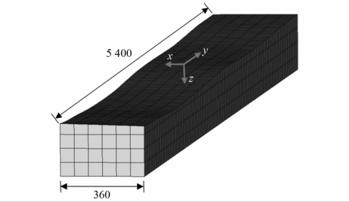
The paper connects physics-based ground-motion simulation with a local seismic-input method, passing regional motions into a tunnel–surrounding rock model. The elongated rock domain and tunnel in the original figure form the local region requiring detailed analysis. Inputs must match not just at one point but also describe variation along the tunnel.
Regional simulation covers the source and a large ground domain; the local model needs detailed rock and lining representation. Connecting these scales requires converting regional motions at the relevant positions into actions the local model can receive. Free-field validation first removes structural complexity to test the transfer itself. Only then is the tunnel added, allowing subsequent response to be attributed to lining–rock interaction rather than input-transfer errors.
Capture both the waveform and permanent displacement
The study first validates input under free-field conditions, then analyses the joint tunnel–ground response and compares acceleration, displacement and stress from different treatments. For fault-crossing problems, displacement remaining at the end of a history is especially important because it represents deformation persisting after the earthquake.
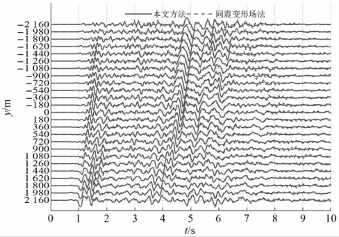
The original figure shows displacement histories at several positions. Each records both the evolving earthquake motion and its final displacement state. Comparing locations reveals whether the tunnel mainly translates as a whole or is pulled unevenly along its length.
Consider the distance between the tunnel ends. If they move similar distances in the same direction, overall translation dominates. If their displacements differ, the intervening lining must stretch, compress or shear. The permanent displacement field determines the final geometry, while dynamic waves determine the repeated actions experienced along the way. Multiple histories combine these two types of information, making the link from input to lining deformation easier to trace.
Translate uneven ground motion into tunnel demands
The results connect near-fault displacement distribution with tunnel forces. In the model studied, relatively high stresses occur at locations including the crown and invert, warranting attention in conjunction with lining details.
The work connects source, site and tunnel scales. Starting from a physically coherent earthquake process, it traces how surrounding rock transmits shaking and fault movement to the lining, providing clearer inputs for force assessment in fault-crossing tunnels.
Examining the crown, sidewalls and invert also links longitudinally varying movement with cross-sectional deformation. As the surrounding ground pulls the tunnel, different directions of lining restraint can concentrate forces in particular regions. Spatial displacement and stress patterns identify these features and provide a mechanical basis for later consideration of reinforcement, flexible details or joints: first establish how deformation is transmitted, then decide where to improve the structure's ability to accommodate it.